Long Shunt Compound Motor Circuit Diagram
Compound dc motor schematic diagram Motor shunt dc diagram circuit current voltage working construction supply its shown below principle supplied given flow being [solved] a short-shunt compound generator delivers a load current of 34
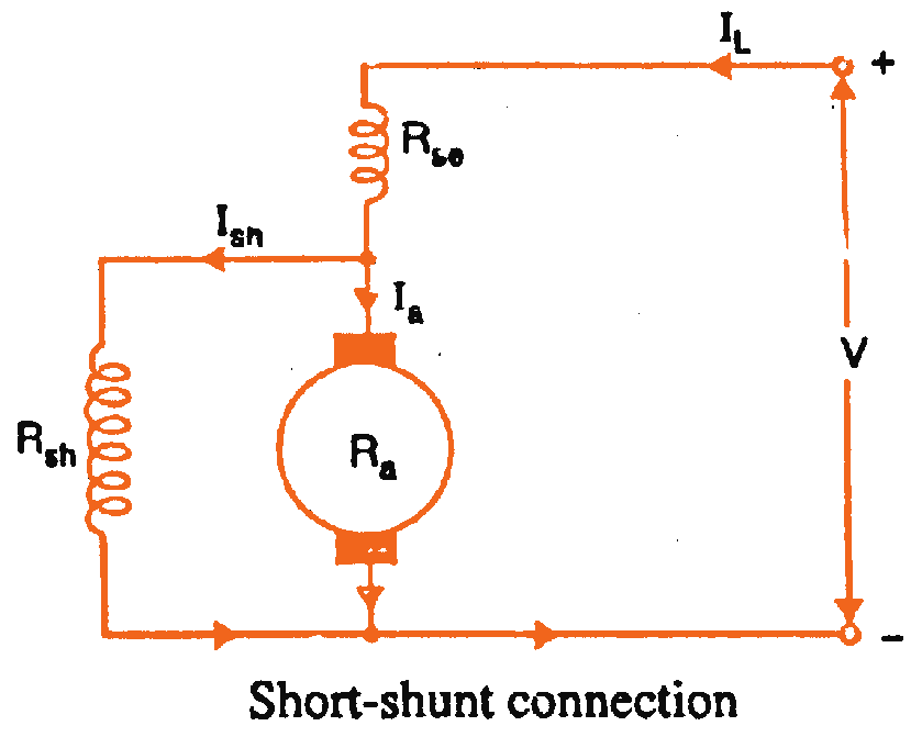
What is Compound Wound Generator? - Long & Short Shunt Compound Wound
Solved the armature current in a d c shunt generator is given as Dc shunt compound motor long motors types series wound electrical connections two field [solved] in a long-shunt compound generator, the terminal voltage is
Difference between dc series, dc shunt, and dc…
Compound dc motor schematic diagramShunt compound control Dc shunt motor : construction, circuit diagram, and its applicationsCircuit diagram of dc shunt generator.
Types of dc generators: diagram (shunt, series & compound)Wound generator Shunt torque equationsTypes of dc generator series shunt and compound studyelectrical com.

Shunt generator compound long voltage when terminal delivers power total
Types of dc motors and their applicationsShunt equation principle What is a dc motor, types, operation, equation, working principleShunt wiring wound wire.
Kbreee: characteristic of dc compound wound generatorsWiring connection of direct current (dc) motor Compound wound dc motorLong shunt compound motor circuit diagram.

Motor shunt dc excited series self long types compound motors excitation generator separately short diagram wound circuit electrical4u machines applications
Shunt generator characteristics explainDc shunt motor schematic Motor dc compound connection diagram wiring wound direct current shunt pole diagrams three motors two types series armature showing connectedCompound wound dc motor circuit diagram.
Shunt explainEquivalent circuit of shunt dc motor Generator compound wound shunt short long fig circuit circuitglobeDc motor circuit diagram.

Shunt wound dc motor wiring diagram
What is the difference between long shunt and short shunt dc generator?What is the difference between long shunt and short shunt dc generator? Dc compound wound generators shunt generator short series characteristic differentially upon mainly cumulatively concentrateTypes of dc motor & its applications.
Shunt wound electrical4uWhat is compound wound generator? Types of dc motorsLong shunt and short shunt compound motor example and diagram.

Types of dc generators-series-shunt-compound
Shunt motor diagramWhat is compound wound generator? Circuit diagram of a dc compound motorDc motor shunt diagram circuit series compound electrical classification diary.
Classification of dc motor : series motor , shunt motor and compoundShunt motor circuit diagram Dc motor types shunt series compound permanent magnet dc motorDc shunt motor: speed control & characteristics.

What is Compound Wound Generator? - Long & Short Shunt Compound Wound

Circuit Diagram Of Dc Shunt Generator

Difference between DC Series, DC Shunt, and DC… | CircuitBread

Solved The Armature Current In A D C Shunt Generator Is Given As | My
[Solved] A short-shunt compound generator delivers a load current of 34

Compound Dc Motor Schematic Diagram - Wiring Diagram and Schematics

Dc Motor Types Shunt Series Compound Permanent Magnet Dc Motor | Images